Computer Notes, Programming codes, Hardware and Networking Tip, Entertainment, Biography, Internet Tip, Tech News, Latest Technology, YouTube,

Articles by "CA"
About RAM Advantages of multiprocessing system Associative memory Binary Number System CA CA Notes Change drive icon change pendrive icon Computer Abbreviation Computer Architecture Computer fundamental MCQ Computer Generation Computer generation computer notes Computer MCQ Computer Network MCQ Computer Operator MCQ Critical Section Critical section in OS Database connectivity in java Deadlock avoidance Deadlock detection algorithm Deadlock Detection and Recovery Deadlock detection method Deadlock Handling Deadlock in OS Deadlock Prevention Deadlock Recovery define object and class Define system cell Descrete Structure Device Driver Device driver in computer device driver in os DFA DFA contains with DFA ends with dfa examples dijkstra's algorithm Discrete Structure Discrete Structure graph theory Download JDBC Driver Download MySql Download PUBG DS DS Notes FCFS Job Scheduling Algorithm Finding shortest path Finite Sate Automata Flynn's Classifications fragmentation in computer fragmentation in harddisk fragmentation in os fragmented memory Full form related to computer Generations of operations Generations of OS Graph theory ICT 1st semester notes Instruction Address Modes Java java array declaration java class and object example Java Database connectivity example java event handling example program Java JDBC Java JMenuBar Java JSP program example java notes java program methods example Java program to create class and object java program to create methods java program to print even number between any two numbers Java programming java programming notes Java programs Java question answer java swing example java swing program to calculate simple interest Java Tutorials JSP program learn qbasic Lekh MCQ MCQ Computer MCQ Operating System memory fragmentation MICT 1st semester notes mict 1st semester operating system notes MICT first semester notes Multiprocessing mutex in os Necessary conditions for deadlock Number System Operating System Operating system notes OS OS Notes OS Numeric pattern printing program in qbasic patterns in qbasic Pipeline Hazards Pipelining Pipelining concept prime or composite in qbasic print patterns qbasic print series in qbasic Printing Series in qbasic PUBG PUBG Mobile PUBG PC PUBG Story qbasic qbasic code qbasic for class 10 qbasic for class 8 qbasic for class 9 qbasic for school QBASIC Pattern printing qbasic pattern printing program qbasic pattern printing programs qbasic pattern types qbasic patterns qbasic programming tutorials qbasic programs qbasic sequence printing programs qbasic tutorials Race Condition in Operating system reverse order in qbasic RISC and CISC RISC Pipeline Scheduling algorithm segmentation in operating system segmentation in os semaphore and mutex Semaphore concept in os Semaphore in os semaphore in os notes semaphore meaning sequential programs in qbasic series in qbasic series printing programs in qbasic shell in operating system shell in os shortest path shortest path algorithm simple interest program in java swing System Bus System Cell Teach Blog Tech Blog Tech School technical school The Shell in Operating system types of fragmentation Types of Multiprocessor types of operating system Types of pipeline hazards View Connected Wifi password Virtual Memory Virtual memory in OS Von Neumann's architecture What is associative memory? what is class? What is computer system? What is Fragmentation? What is jsp? what is object? What is process? What is segmentation What is System Cell What is Thread? what is virtual memory in computer What is virtual memory? पब्जी गेम

Multiprocessing is the use of two or more central processing unit within a single computer system. The term also refers to the ability of a system to support more than one processor or the ability to allocate task between them. Multiprocessor is a computer system having two or more processing units each sharing main memory and peripherals, in order to simultaneously process programs.


Multiprocessing however means using more than one processor. However, multiprocessor or parallel system are increasing in importance nowadays. These systems have multiple processors working the parallel that share the computer clock, memory bus, peripheral devices etc. The following figure demonstrate the multiprocessor architecture as

Types of Multiprocessors

There are mainly two types of multiprocessor i.e symmetric and asymmetric multiprocessors.
1. Symmetric Multiprocessor
In this type of multiprocessor each runs an identical copy of the OS and these copies communicate with one another as needed. All Processor are peers. Examples are Windows NT, Sun Solaries, Digital Unix, OS/2 and Linux.

2. Asymmetric multiprocessor
In this multiprocessor each processor is assigned a specific task. A master processor controls the system; the other processor look to the master for instructions or predefined tasks. It defines a master-slave relationship. Example Sun OS version 4.
Asymmetric multiprocessor was the only one type of multiprocessor available before symmetric multiprocessor were created. Now also, this has cheaper option.


Advantages of multiprocessor systems 

  • More reliable system (Ability to continue working if any CPU fails) 
  • Enhanced Throughput 
  • More Economic systems
  • Increased Expense 
  • Complicated Operating system required 
  • Large main memory required 

Flynn's Classification 


  • In 1966, Flynn's proposed or classified the computer architecture into 4 types. So this concept known as Flynn's classification. 
  • This classification has been used as a tool in the design of modern processors and their functionalities. 
  • Due to Flynn's classification the multiprocessing and multiprocessing concept has evolved. 
  • Flynn's classified the system into four types that is based upon the number of current instruction streams and data streams available in the architecture . 

Flynn's Classifications


Single Instruction Single Data (SISD) System 


  • It is Uni-processor machine 
  • It executes a single instruction which operate on a single data stream. 
  • In SISD, machine instructions are processed in a sequential manner, So it is known as sequential computers. 
  • It this the speed of the processing element in the SISD model is limited or dependent on the rate at which the information is transformed. 
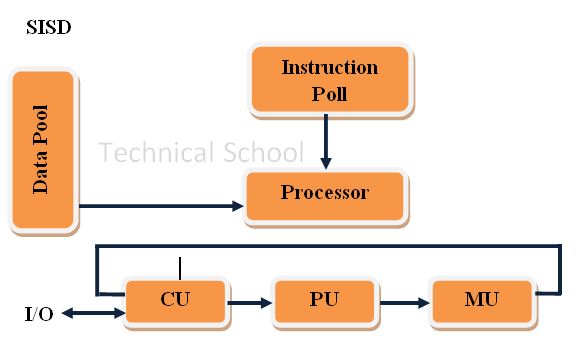
SISD Uni-Processor Architecture
Captions 
CU - Control Unit                    PU - Processing Unit
MU - Memory Unit                 IS - Instruction Stream  
DS - Data Stream 

Single Instruction Multiple Data (SIMD) Systems 


  • SIMD is multiprocessor system. 
  • It execute the instruction on all the CPU's but operate on different data streams. 
  • SIMD model is well suited to scientific operations. So that the information can be passed to all the processing elements organized data elements of vectors can be divided into multiple sets (N sets for N PE system) and each PE can process on data set. 
  • SIMD system is cray's vector processing machine. 
SIMD Architecture (With Distributed Memory) 
Captions : 
CU - Control Unit                     PU - Processing Unit
MU - Memory Unit                  IS - Instruction Stream
DS - Date Stream                      PE - Processing Element 
LM - Local Memory 

Multiple Instruction Single Data (MISD) Systems 


  • It is a multiprocessor machine 
  • It execute different instructions on different PE (Processing Element) but all of the operates on the same data set. 
                      Example ; sin(x) + cos(x) + tan(x)
  • It performs different operations on the same data set. 
  • The computer system built using the MISD model are not useful in most of the applications. 
MISD Architecture (The systolic Array) 
Captions
CU - Control Unit,          PU- Processing Unit,            MU- Memory Unit, 
IS - Instruction Stream,          DS-Data Stream,             PE - Processing Element
LM - Local Memory 


Multiple Instruction Multiple Data (MIMD) Systems)


  • This system is multiprocessor machine
  • It executes multiple instructions on multiple data sets. 
  • In this, each processing elements (PE) has separate instruction and data streams
  • The computer system built using the MIMD model are capable for all types of applications
  • In this processing elements (PE) work asynchronously while SIMD and MISD machine doesn't work asynchronously 
MIMD Architecture (With shared Memory)
Captions: 
CU - Control Unit                 PU - Processing Unit
MU - Memory Unit               IS - Instruction Stream
DS - Data Stream                  PE - Processing Element
LM - Local Memory

Traditional memory stores data at a specific address and "recalls" that data later if the address is specified. Instead of an address, associative memory can recall data if a small portion of the data itself is specified.


Associative memory is often referred to as content. Addressable memory (CAM). In associative memory, any stored items can be accessed by using the contends of item. Items are stored in an associative memory have two field format, key and data.
Associative searching is based on simultaneous matching of key to be searched with stored key associated with each line of data.


The following diagram shows the block representation of an associative memory.
From the block diagram we can say that an associative memory consists of a memory array and logic for 'm' words with 'n' bits per word. 


The functional registers like the argument register A and key register K each have n bits, are for each bit of a word. The match register m consist of M bits, one for each memory word.

Pipeline hazards are situations that prevent the next instruction in the instruction stream from executing during its designated clock cycles. In another word, any condition that causes a stall in the pipeline operations can be called a hazard. There are mainly three types of hazards, they are:
  1. Data Hazards 
  2. Structural Hazards
  3. Control Hazards 


Data Hazards
It arises when instructions depend on the result of previous instruction but the previous instruction is not available yet.

Structural Hazards:
They arise when there are resource conflicts that prevents hardware to execute simultaneous execution of instruction. For e.g. Lets say the hardware has a register file which has a limitation of only one read or write in a cycle. If there is an instruction that needs to read from this register file while another instruction needs to write to this register file, only one can execute because of conflict.

Control Hazards
These hazards arise as a result of any type of branch instruction. Till the branch is completely executed. The branch is completely executed, the stream of following instructions will not be known completely.


Reduced instruction set computer (RISC).
 The main characteristics of RISC pipeline is to use an efficient instructions pipeline. In case of RISC pipeline, the instruction pipeline can be implemented with only two or three segments where segments 1 fetches the instructions from the memory.

Segment 2 executes the instruction in the ALU, and segment 3 may be used to store the results of the ALU operation in a particular register.


Parallel processing systems are designed to speed up the execution of programs by dividing the program into multiple fragments and processing these fragments simultaneously such systems are known as tightly coupled systems.


Parallel computing is an evolution of serial computing where the jobs are broken into discrete parts that can be executed currently. Each part is further broken down to a series of instructions. Instructions from each part execute simultaneously on different CPU's.


Parallel systems are more difficult to program than computers with a single processor because the architecture of parallel computers varies accordingly and the processes of multiple CPU's must be co-ordinates and synchronized.

Pipeline is the process of accumulating instruction from the process through a pipeline. It allows strong and executing instructions in an orderly process. It is also known as pipeling process.

Pipeline is a technique where multiple instructions are overlapped during execution. Pipeline is divided into stages and these stages are connected with one another to form a pipe like structure. Instructions entered from one end and exit from another end.

Pipelining increases the overal instruction throughput. 


  1. Arithmetic Pipeline 
  2. Instruction Pipeline 
Arithmetic Pipeline 
Arithmetic pipeline unit are found in usually in most of the high speed computers. Floating point operations, multiplication of fixed-point numbers, and similar computation in scientific problem. 
For example : the input to floating point adder pipeline is : 
x = A*Z^a
y = B*2^b

Here, A and B are significant digits of floating point number, while a and b are exponents.


Instruction Pipeline
In this a stream of instructions can be executed by overlapping fetch, decode and execute phases of an instruction cycle. This type of technique is used to increases the throughput of the computer system.

An instruction pipeline reads instruction from the memory while previous instructions are being executed in other segments of the pipeline. Thus we can execute multiple instructions simultaneously. The pipeline will be more efficient if the instruction cycle is divided into segment of equal duration.


The interconnection structure must support the following types of module

  • Memory to processor : the CPU reads an instruction or data from memory
  • Processor to memory : the CPU write data to memory 
  • I/O to processor : the CPU reads data from the I/O device via the I/O module 
  • Processor to I/O
  • I/O to or from memory : An I/O module is allowed to change data directly with memory without going through the processor using DMA (Direct Memory Access) 


Bus Interconnection 
  • A bus is a  communication pathway consisting of lines and it is connecting two or more devices. 
  • A bus is considered as a shared transmission medium allowing multiple devices to connect to it
  • However, only one device at a time can successfully transmit 
  • Several lines of the bus can be used to transmit binary digits simultaneously. 
  • For example : 
    • An 8 bit unit of data can be transmitted over 8-bus lines. 
  • A bus that connect the major computer components (CPU, Memory, I/O) is called System Bus. 
  • A system bus may consists of 50 or hundreds of separate lines. Each line has a particular functions. 
  • The interconnection structures are based on the use of one or more system buses. 
  • Bus lines can be classified based 3 functional groups. 

Bus lines can be classified based on 3 functional groups. 
  1. Data Lines
  2. Address Lines 
  3. Control Lines
Data Lines
  • It provide pathway for moving data between system modules. 
  • These lines are called Data Bus
  • The Lines (32 to hundred) referred to as the width of the bus
  • The width determines the overall system performance. 
e.g If the data bus is 8 bit wide, and each instruction is 16 bit long, then the processor must access the memory module twice during each instruction cycle. 

Address Line

  • It is used to determine the source or destination of the data on the data bus. 
  • For example : 
    • The CPU puts the address of the desired word to be read from/or written to memory on the address lines. 
  • The width of an system bus determine the maximum addressable memory
  • The address lines are also used to address I/O ports. 

Control Lines

  • Control lines are used to hold control signals to control the access and the use of data and address lines since these lines are shared by all components
  • Control signals transmit command and timing information between system components. 
    • Timing signal indicate the validity of data and address information 
    • Command signals specifies the type of operations to be performed

Main operation of Bus 
If a module wishes to send data to another module it must do two things.

  • Obtain the use of the bus
  • Transfer data via the bus
If a module wishes to request data from another module it must do two things. 
  • Obtain the use of the bus
  • Transfer a request to the other module over appropriate control and address lines
  • Wait for the other module to send the data 

In a shared memory multiprocessor with a separate cache memory for each processor, it is possible to have many copies of any one instruction operand. One copy in the main memory and one in each cache memory. When one copy often operand is changed, the other copies of the operand must be changed.
For example : 

In the above illustration, consider both the processor have a cache copy of a particular memory block from previous read. Let suppose processor 1 updates or change the cache block, after that it change the memory block using any one methods (write through, write block or instruction flow). But processor doesn't get any notification or signals of update/change. So here data inconsistency occurs, it is called cache coherence. It happens in multiprocessor system. 


Cache coherence occurs in the following conditions 
* Inconsistency in sharing of writable data


* Inconsistency in process migration

* IO Activity 

There are three distinct levels of cache coherence:
  1. Every write operation appears to occur instantaneously.
  2. All processes see exactly the same sequence of changes of values for each separate operand.
  3. Different processes may see an operand assume different sequences of values. (This is considered non-coherent behavior.)

Types of cache coherence solution
To avoid cache coherence we have two types of solution
  1. Software Solution
  2. Hardware Solution
Software Solution
- Problem is managed completely by compiler and OS. 
- No additional circuitry
- In this approach, compiler marks the data which are likely to be changed, the OS prevent those data to be cached.  

Hardware Solution
- Hardware solution provide dynamic recognition at run time of potential inconsistency conditions. Because the problem is only dealt with when it actually arises, there is more effective use of caches, leading to improved performance over a software approaches. 
- Hardware schemes can be divided into two categories 
  1. Directory Protocol 
  2. Snoopy protocols

Snooping
- Used with low-end MPs
- Few processors 
- Centralized memory
- Bus-based
- Distributed implication : responsibility for maintaining coherence lies with each cache

Direct
- Used with higher-end MPs
- More processors 
- Distributed memory
- Multi-path interconnect
- Centralizing for each address : responsibility for maintaining coherence lies with the directory for each address   


Define arithmetic pipelining. Explain pipelining hazards with examples. 


Pipelining is a technique where multiple instructions are overlapped during execution. Pipeline is divided into stages and these stages are connected with one another to form a pipe like structure. Instructions enter from one end and exit from another end. There are two types of pipeline. 
  1. Arithmetic Pipeline
  2. Instruction Pipeline 
Arithmetic pipelines are usually found in most of the computers. They are used for floating point operations, multiplication of fixed point numbers etc.
Pipeline hazards are situations that prevent the next instruction in the instruction stream from 


Pipelining Hazards 
Pipeline hazards are situations that prevent the next instruction in the instruction stream from executing during its designated clock cycles. In another word, any condition that causes a stall in the pipeline operations can be called a hazard. There are mainly three types of hazards, They are : 

  1. Data Hazards
  2. Control Hazards or instruction Hazards
  3. Structural Hazards.

Example:  
A=3+A
B=A*4

For the above sequence, the second instruction needs the value of ‘A’ computed in the first instruction. Thus the second instruction is said to depend on the first. In this situation data hazards is arises.  A data hazard is any condition in which either the source or the destination operands of an instruction are not available at the time expected in the pipeline.

Define memory hierarchy. Explain cache memory mapping functions with example. 


Memory hierarchy is a concept that is necessary for the CPU to be able to manipulate data. In computer architecture, the memory hierarchy separates computer storage into a hierarchy based on response time. Since response time, complexity, and capacity are related, the levels may also be distinguished by their performance and controlling technologies. The following figure shows the hierarchy of memory in computer. 
Cache is used by the CPU for memory which is being accessed over and over again. Instead of pulling it every time from the main memory, it is put in cache for fast access. It is also a smaller memory, however, larger than internal register.
Cache memory is used to reduce the average time to access data from the Main memory. The cache is a smaller and faster memory which stores copies of the data from frequently used main memory locations.
There are different levels of catch memory. Level 1, Level 2, Level 3 etc.  Levels of catch is based on the architecture of computer. 

Cache Mapping
There are three different types of mapping used for the purpose of cache memory which are as follows:

  1. Direct mapping
  2. Associative mapping and 
  3. Set-Associative mapping. 

Direct Mapping
Direct catch mapping

  • The simplest way to determine cache locations in which store Memory blocks is direct Mapping technique.
  • In this block J of the main memory maps on to block J modulo 128 of the cache. Thus main memory blocks 0,128,256,….is loaded into cache is stored at block 0. Block 1,129,257,….are stored at block 1 and so on.
  • Placement of a block in the cache is determined from memory address. Memory address is divided into 3 fields, the lower 4-bits selects one of the 16 words in a block.
  • When new block enters the cache, the 7-bit cache block field determines the cache positions in which this block must be stored.
  • The higher order 5-bits of the memory address of the block are stored in 5 tag bits associated with its location in cache. They identify which of the 32 blocks that are mapped into this cache position are currently resident in the cache.
  • It is easy to implement, but not Flexible


Explain the Organization of micro-programmed control design. 


Micr-program is a process of writing microcode for a microprocessor. Microcode is low-level code that defines how a microprocessor should function when it executes machine-language instructions. Typically, one machine language instruction translates into several microcode instruction, on some computers, the microcode is stored in ROM and can not be modified.

Micro programmed Control Unit:

  • A control unit with its binary control values stored as words in memory is called as micro programmed control. Each word in the control memory contains micro instruction that specifies one or more micro operations for the system. A sequence of micro instructions constitutes a micro program.
  • Micro programmed implementation is a software approach in contrast to the hardwired approach.
  • It deals with various units of software but at the micro level i.e. micro-operation, micro-instruction, micro-program etc.
  • Different key elements used for implementation of a control unit using micro programmed approach is shown in fig. below:
Control Address Register (CAR)

It contains the address of next micro instruction to be read. This is similar to the program counter(PC) which stores the address of the next instruction.


Control Memory
The set of micro instruction is stored in control Memory (CM) also called as control store.

Control Buffer Register(CBR)
When microinstruction is read from the control memory, it is transferred to a control Buffer Register (CBR), which is similar to the instruction Register (IR) that stores the opcode of the instruction read from the memory.

Sequencing
It loads the control Address register with the address of the next instruction to be read abd issues a read command to control memory.


Explain the instruction execution cycle with state diagram. 


The instruction cycle is the cycle which the central processing unit (CPU) follows from boot-up until the computer has shut down in order to process instructions. It is also known as the fetch–decode–execute cycle or simply the fetch-execute cycle. It is composed of three main stages: the fetch stage, the decode stage, and the execute stage. In an improved instruction execution cycle, we can introduce a next cycle known as the interrupt cycle. 


Fetch 
It is the process of obtaining instructions from the memory. The next instruction is fetched from the memory address that is currently stored in the PC (program counter) and stored into the IR (instruction register). At the end of the fetch operation, the PC points to the next instruction that will be read at the next cycle.

Decode 
It is the stage of understanding the instructions. During this stage the encoded instruction present in the instruction register is interpreted by the decoder.


Execute
In this stage control unit sends the instructions and data to ALU for taking suitable action on the instruction and writing the result back to a register.  If the ALU is involved, it sends a condition signal back to the CU. The result generated by the operation is stored in the main memory or sent to an output device. 

Repeats Cycle
Once the execution cycle is complete, It repeats the same process/cycle for the next instruction. 


What is computer system? Discuss its components. Explain John Von Neumann's architecture of computer system. 


A computer system is a set of integrated devices that input, output, process, and store data and information. Computer systems are currently built around at least one digital processing device. There are five main hardware components in a computer system: Input, Processing, Storage, Output and Communication devices.

Input
Input means data and instruction given to the computer which is most essential for producing meaningful and useful output. The unit which is used to give input to the computer system is called input unit and it is formed by various input devices attached to the computer such as keyboard, mouse, joystick, trackball touch screen, MICR (Magnetic Ink Character REader) etc into computer understandable form. The input unit establishes the communication link between the user and the computer system. 

Processing
Processing unit is also called 'Central Processing Unit' and it is the control center for a computer. It guides, directs and governs all operations and components inside the computer. It is considered as brain of computer. It is linked with various peripheral devices including I/O devices, secondary storage and memory unit. it performs arithmetic operations, logical comparison, transfer information between all parts of computer and executes instructions. CPU consists of ALU, CU and Registers. 

Output
Output is the processed data which is very useful and meaningful to us and we can get it from the computer in the form that we want. The unit which is used to provide output is called output unit. It is always in the form of human readable or understandable. There are various types of output devices such as Monitor, Printer, Plotter, Speakers etc. 

Memory/Storage Unit
A storage device is any computing hardware that is used for storing, porting and extracting data files and objects. It can hold and store information both temporarily and permanently, and can be internal or external to a computer, server or any similar computing device.  Data and instruction are stored in memory in the binary form. 


Von Neumann Architecture
Von Neumann architecture is based on the stored-program computer concept, where instruction data and program data are stored in the same memory.  This design is still used in most computers produced today. This architecture was first published by John von Neumann in 1945.

Von Neumann Architecture
His computer architecture design consists of a Control Unit, Arithmetic and Logic Unit (ALU), Memory Unit, Registers and Inputs/Outputs.


CPU (Central Processing Unit)
The CPU is an electronic circuit which is responsible for executing the instructions of a computer program. Sometimes it is also referred to as the microprocessor or processor. It contains ALU, CU and Registers. 

Registers 
Registers are high speed storage areas in the CPU.  All data must be stored in a register before it can be processed. Some registers are 
  • MAR (Memory Address Register) 
  • MDR (Memory Data Register) 
  • AC (Accumulator) 
  • PC (Program Counter) 
  • CIR (Current Instruction Register) 
ALU (Arithmetic and Logic Unit) 
The ALU allows arithmetic (add, subtract etc) and logic (AND, OR, NOT etc) operations to be carried out.

CU(Control Unit) 
The control unit controls the operation of the computer’s ALU, memory and input/output devices, telling them how to respond to the program instructions it has just read and interpreted from the memory unit.

MU (Memory Unit)
The memory unit consists of RAM, sometimes referred to as primary or main memory.  Unlike a hard drive (secondary memory), this memory is fast and also directly accessible by the CPU.

Buses 
Buses are the means by which data is transmitted from one part of a computer to another, connecting all major internal components to the CPU and memory. There are three types of buses 
  • Address Bus (Carries the addresses of data) 
  • Data Bus (Carries data between different units) 
  • Control Bus (Carries control signals from CPU to control the activities) 

As we need a highway to travel from one place to another place. Similarly, the input and output of computer system also need a path to transmit data, information and control from one device to another device. The data transmit from input device to CPU, CPU to memory are common examples of system bus. 

The path through which data and instruction flow is called bus of computer. It is a collection of wires, chips and slots inside the computer through which data and information are transmit from one part of computer to another.

Normally, Bus is available from 1 bit and above. The width of the bus determines how much data can moved at a time. Nowadays, PATA cables are replaced by SATA cables because of faster and small in size. These are also a way of transferring data and information from HDD to memory. Beside these cables there are numbers of buses inside the computer system (motherboard). There are three types of System bus they are : 

1) Address Bus 

The pathway through which transmit of address of memory location is called address bus. All types of memory devices have microscopic memory cells which are identified with unique humans known as memory address or memory locations. When the CPU reads data or instruction from memory or writes data to memory, it must specify the address of the memory location it is going to access. Unlike the other buses, the address bus always receive memory location from the CPU. There is one way flow in address bus. 

2) Data Bus

The pathway (circuit / chips / wires / slots) through which transmit of data from one memory location to other is called Data Bus. When the CPU fetches data from memory, it first output the memory address on its address bus. Then the data bus. When writing data to memory, the CPU first outputs the address onto the address bus, then output the data onto the data bus. Memory the reads and stores the data to the proper location. The data flows in bidirectional way. 

3) Control Bus

The pathway (circuit / chips / wires / slots) through which transmit of control signal to operate and control devices and software is called control bus. It is different from other two buses. The control bus is the collection of individual control signals for timing and controlling function sent by the control unit to other unit of the system. These signals indicate where data is to read or written, whether the CPU is accessing memory or an input/output device, and whether the I/O device or memory is ready to transfer data.  

Based on the period of development and the features incorporated the computer are classified into different generations from first generation to fifth generation computers.

First Generation Computer 

Computers which were made approximately between 1941 and 1955 A.D. are classified as the first generation computer. Vacuum Tube is the main technology, which was developed by Lee de forest in 1908 A.D. 
  • Technology : Vacuum Tube
  • Processing Speed : processing speed was measured in millisecond
  • I/O Devices : Punch card was used as input / output devices 
  • Compute Type : Computers were electron mechanical 
  • Memory : Vacuum tube was used as memory device
  • Storage device : First punch card and later magnetic drum
  • Operation Mode : Computer should be setup manually as there was no operating system
  • Reliability and Accuracy : Not fully reliable and accurate 
  • Programming language : Machine level language 
  • Size and cost : Very large in size and expensive 
  • Availability : available to the military purpose and university research only 
  • Power and Heat : Consumed a lot of a electricity and emitted a lot of heat
  • Portability : Computer were not portable 
  • Example : Mark I, ABC, ENIAC etc. 


Second Generation Computer 

Computer which were made approximately between 1955 to 1964 and having the transistor and diodes as main memory device are classified as the second generation computer. Transistor was designed by Walter Brattain, John Bardeen and William Sockley in 1947 A.D. 
The main features of computer generation are as follows. 
  • Technology : Transistor (Main component)
  • Processing Speed : Measured in Microsecond
  • I/O Devices : punch card was used as input / output device
  • Memory: Magnetic core memory is used as internal memory 
  • Storage device : Magnetic tape
  • Operation mode : Should set up manually as there was not os. 
  • Reliability and Accuracy : More reliable and accurate then first generation computer. 
  • Programming language : Assembly and high Level language such as FORTRAN, ALGOL, COBOL etc. 
  • Size & cost : Smaller and less expensive then first generation 
  • Availability : Available for general purpose 
  • Power consumption and Heat : Power consumption and heat emission was less then first generation computer. 
  • Portable : Not portable 
  • IBM 1401, ICL 2950/10, IBM 1620 etc. 

Third Generation Computer 

The computers which were made approximately between 1964 to 1975 and having IC's technology as memory and processing devices are classified as third generation computer. The first IC was developed by Jack Kilby and Robot Noyce in 1985. Later Robert Noyce established Intel company. 
  • Technology : IC (Integrated Circuit) 
  • Processing Speed : Faster than previous generation computer 
  • I/O devices : Keyboard and Monitor
  • Computer Type : Electronic 
  • Memory : Semiconductor memory (Primary memory)
  • Storage Devices : Magnetic disk (Secondary memory)
  • Operation Mode : Os was introduced for automatic and multi programming. 
  • Reliability and accuracy : Fully reliable and accurate 
  • Programming language : High level language for computer programming 
  • Size and cost : Smaller in size and less expensive then previous generations of computer 
  • Availability : Available for general purpose as well as for personal use. 
  • power consumption and heat emission : Power consumption and heat emission was less than previous generation computer
  • Potable : Become portable computer because of development of Desktop and Laptop computer 
  • Example : IBM 360 Series, ICL 1900 etc, UNIVAC etc. 


Fourth Generation Computer  

The computer which were made approximately between 1975 to till now and having microprocessor as CPU and VLSI and ULSI technology in IC as memory device and classified as fourth generation computer. 
- Microprocessor is a chip in which millions of components are integrated together in different layers. 
- First commercial microprocessor was Intel 4004 made by Intel corporation in 1971 AD. It was 4 bit processor. 
The main features of fourth generation computer are
  • Technology : IC's and Microprocessor 
  • Processing speed : Faster then previous generations
  • I/O devices : Fourth refined and invented various devices such as scanner, touch screen, printer etc. 
  • Computer type : Electronic 
  • Memory : Semiconductor memory with huge capacity 
  • Storage device : Magnetic and optical disk with large storage capacity for secondary storage device. 
  • Operation mode : Multi programming, multi processing, multimedia and distributed operating system become possible. 
  • Reliability and accuracy : Fully reliable and accurate 
  • Programming language : advance HLL and 4GL for application and database programming have been used. 
  • Size and cost : Smaller and less expensive then previous generations of computer
  • Availability : General purpose as well as special purpose 
  • Power consumption and heat emission : It has been less then previous generation of computer
  • Portable : Because portable off development of personal or Desktop computer, Laptop, Notebook, PDA etc. 
  • Example : Acer ASPIRE 5741, Apple MacBook Air, Dell Inspiration 1400 etc. 

Fifth Generation Computer 

Although the computer of this generation have not come yet in reality, but computers scientist are trying since 1990 A.d. It is said that the computer of this generation will use AI (Artificial Intelligence) and bio-chips as memory devices so that they can think and decide this like a human being. 
Features of fifth generation computer are as follows
  • They will be super conductor memory like bio-chips that the speed will be very fast. 
  • The computer will be intelligent and knowledge base because of AI. 
  • Instead of HLL, natural languages will be used such as English, Nepali, Hindi for giving instruction
  • this computer will have power of seance, logic and decision making capacity  


In computer CPU the micro-operations are detailed low-level instructions which is used in some designs to implement complex machine instructions. Usually, micro-operations perform basic operations on data stored in one or more register, including transferring data between registers or between registers and external buses of the CPU and performing arithmetic or logical operations on registers. The execution of micro-operations is performed under control of the CPU’s control unit which decides on their execution while performing various optimizations such as reordering, fusion and caching of the operations.


The operations executed on data stored in registers are called micro-operations. A micro-operation is an elementary operation performed on the information stored in one or more registers. The functions built into registers are examples of micro operations, They are Shift, Load, Clear, Increment, add, subtract, complement, and, or, xor etc ..


There are Four Types of Micro Operations 


1.      Register transfer micro-operations

2.      Arithmetic micro-operations

3.      Logic micro-operations

4.      Shift micro operations


1) Register transfer micro operation

Register transfer language is a kind of intermediate representation (IR) that is very close to assembly language, such as that which is used in a compiler. It is used to describe data flow at the register transfer level of an architecture. It is a convenient tool for describing the internal organization of digital computers in concise and precise manner. These types of micro operations are used to transfer binary information from one register to another. Often the names indicate function:

  • MAR  – Memory Address Register
  • PC - Program Counter
  • IR - Instruction Register
In this case the contents of register R1 are copied (loaded) into register R2

2) Arithmetic Micro-Operations

These micro-operations are used to perform some arithmetic operations on numeric data stored in the registers. A micro operation is an elementary operation performed on the information stored in one or more registers. The micro operation in digital computers is of 4 types:   Addition, Subtraction, Increment, and Decrement
  1.  Addition:-
R1 = A + B
R3 = R1 + R2
  1. Subtraction: -
R1 = R2 – R3
Subtraction operation also can be performed on 2’s complement  R = R1 + R2’ + 1
  1. Increment:-
R1 = R1 + 1,   R2 = R2 + 1
  1. Decrement:-
R1 = R1 – 1,   R2 = R2 – 1


3) Logic Micro-Operations

These micro operations are used to perform bit style operations or manipulations on non-numeric data. In computer CPU, micro-operations are the functional or atomic operations of a processor. Logic micro operations are bit-wise operations, i.e., they work on the individual bits of data. These are useful for bit manipulations on binary data and also useful for making logical decisions based on the bit value.

        R1 = R1 XOR R2

        R2 = R3 AND R4

4) Shift Micro-Operations

These are used for serial transfer of data. That means we can shift the contents of the register to the left or right. In the shift left operation the serial input transfers a bit to the right most position and vice versa.

There are three types of shifts as follows:
a) Logical Shift

It transfers 0 through the serial input. The symbol "shl" is used for logical shift left and "shr" is used for logical shift right.

              R1 ← she R1
              R1 ← she R1

The register symbol must be same on both sides of arrows.


b) Circular Shift

This circulates or rotates the bits of register around the two ends without any loss of data or contents. In this, the serial output of the shift register is connected to its serial input. "cil" and "cir" is used for circular shift left and right respectively.

              R1 = cir R1
              R2 = cil R2


c) Arithmetic Shift

This shifts a signed binary number to left or right. An arithmetic shift left multiplies a signed binary number by 2 and shift left divides the number by 2. Arithmetic shift micro-operation leaves the sign bit unchanged because the signed number remains same when it is multiplied or divided by 2.

              R ← ashl R (arithmetic shift left R (register))

              R ← ashr R (arithmetic shift right R (register))
 

MKRdezign

Contact Form

Name

Email *

Message *

Powered by Blogger.
Javascript DisablePlease Enable Javascript To See All Widget