Computer Notes, Programming codes, Hardware and Networking Tip, Entertainment, Biography, Internet Tip, Tech News, Latest Technology, YouTube,

Latest Post
About RAM Advantages of multiprocessing system Associative memory Binary Number System CA CA Notes Change drive icon change pendrive icon Computer Abbreviation Computer Architecture Computer fundamental MCQ Computer Generation Computer generation computer notes Computer MCQ Computer Network MCQ Computer Operator MCQ Critical Section Critical section in OS Database connectivity in java Deadlock avoidance Deadlock detection algorithm Deadlock Detection and Recovery Deadlock detection method Deadlock Handling Deadlock in OS Deadlock Prevention Deadlock Recovery define object and class Define system cell Descrete Structure Device Driver Device driver in computer device driver in os DFA DFA contains with DFA ends with dfa examples dijkstra's algorithm Discrete Structure Discrete Structure graph theory Download JDBC Driver Download MySql Download PUBG DS DS Notes FCFS Job Scheduling Algorithm Finding shortest path Finite Sate Automata Flynn's Classifications fragmentation in computer fragmentation in harddisk fragmentation in os fragmented memory Full form related to computer Generations of operations Generations of OS Graph theory ICT 1st semester notes Instruction Address Modes Java java array declaration java class and object example Java Database connectivity example java event handling example program Java JDBC Java JMenuBar Java JSP program example java notes java program methods example Java program to create class and object java program to create methods java program to print even number between any two numbers Java programming java programming notes Java programs Java question answer java swing example java swing program to calculate simple interest Java Tutorials JSP program learn qbasic Lekh MCQ MCQ Computer MCQ Operating System memory fragmentation MICT 1st semester notes mict 1st semester operating system notes MICT first semester notes Multiprocessing mutex in os Necessary conditions for deadlock Number System Operating System Operating system notes OS OS Notes OS Numeric pattern printing program in qbasic patterns in qbasic Pipeline Hazards Pipelining Pipelining concept prime or composite in qbasic print patterns qbasic print series in qbasic Printing Series in qbasic PUBG PUBG Mobile PUBG PC PUBG Story qbasic qbasic code qbasic for class 10 qbasic for class 8 qbasic for class 9 qbasic for school QBASIC Pattern printing qbasic pattern printing program qbasic pattern printing programs qbasic pattern types qbasic patterns qbasic programming tutorials qbasic programs qbasic sequence printing programs qbasic tutorials Race Condition in Operating system reverse order in qbasic RISC and CISC RISC Pipeline Scheduling algorithm segmentation in operating system segmentation in os semaphore and mutex Semaphore concept in os Semaphore in os semaphore in os notes semaphore meaning sequential programs in qbasic series in qbasic series printing programs in qbasic shell in operating system shell in os shortest path shortest path algorithm simple interest program in java swing System Bus System Cell Teach Blog Tech Blog Tech School technical school The Shell in Operating system types of fragmentation Types of Multiprocessor types of operating system Types of pipeline hazards View Connected Wifi password Virtual Memory Virtual memory in OS Von Neumann's architecture What is associative memory? what is class? What is computer system? What is Fragmentation? What is jsp? what is object? What is process? What is segmentation What is System Cell What is Thread? what is virtual memory in computer What is virtual memory? पब्जी गेम


In computer CPU the micro-operations are detailed low-level instructions which is used in some designs to implement complex machine instructions. Usually, micro-operations perform basic operations on data stored in one or more register, including transferring data between registers or between registers and external buses of the CPU and performing arithmetic or logical operations on registers. The execution of micro-operations is performed under control of the CPU’s control unit which decides on their execution while performing various optimizations such as reordering, fusion and caching of the operations.


The operations executed on data stored in registers are called micro-operations. A micro-operation is an elementary operation performed on the information stored in one or more registers. The functions built into registers are examples of micro operations, They are Shift, Load, Clear, Increment, add, subtract, complement, and, or, xor etc ..


There are Four Types of Micro Operations 


1.      Register transfer micro-operations

2.      Arithmetic micro-operations

3.      Logic micro-operations

4.      Shift micro operations


1) Register transfer micro operation

Register transfer language is a kind of intermediate representation (IR) that is very close to assembly language, such as that which is used in a compiler. It is used to describe data flow at the register transfer level of an architecture. It is a convenient tool for describing the internal organization of digital computers in concise and precise manner. These types of micro operations are used to transfer binary information from one register to another. Often the names indicate function:

  • MAR  – Memory Address Register
  • PC - Program Counter
  • IR - Instruction Register
In this case the contents of register R1 are copied (loaded) into register R2

2) Arithmetic Micro-Operations

These micro-operations are used to perform some arithmetic operations on numeric data stored in the registers. A micro operation is an elementary operation performed on the information stored in one or more registers. The micro operation in digital computers is of 4 types:   Addition, Subtraction, Increment, and Decrement
  1.  Addition:-
R1 = A + B
R3 = R1 + R2
  1. Subtraction: -
R1 = R2 – R3
Subtraction operation also can be performed on 2’s complement  R = R1 + R2’ + 1
  1. Increment:-
R1 = R1 + 1,   R2 = R2 + 1
  1. Decrement:-
R1 = R1 – 1,   R2 = R2 – 1


3) Logic Micro-Operations

These micro operations are used to perform bit style operations or manipulations on non-numeric data. In computer CPU, micro-operations are the functional or atomic operations of a processor. Logic micro operations are bit-wise operations, i.e., they work on the individual bits of data. These are useful for bit manipulations on binary data and also useful for making logical decisions based on the bit value.

        R1 = R1 XOR R2

        R2 = R3 AND R4

4) Shift Micro-Operations

These are used for serial transfer of data. That means we can shift the contents of the register to the left or right. In the shift left operation the serial input transfers a bit to the right most position and vice versa.

There are three types of shifts as follows:
a) Logical Shift

It transfers 0 through the serial input. The symbol "shl" is used for logical shift left and "shr" is used for logical shift right.

              R1 ← she R1
              R1 ← she R1

The register symbol must be same on both sides of arrows.


b) Circular Shift

This circulates or rotates the bits of register around the two ends without any loss of data or contents. In this, the serial output of the shift register is connected to its serial input. "cil" and "cir" is used for circular shift left and right respectively.

              R1 = cir R1
              R2 = cil R2


c) Arithmetic Shift

This shifts a signed binary number to left or right. An arithmetic shift left multiplies a signed binary number by 2 and shift left divides the number by 2. Arithmetic shift micro-operation leaves the sign bit unchanged because the signed number remains same when it is multiplied or divided by 2.

              R ← ashl R (arithmetic shift left R (register))

              R ← ashr R (arithmetic shift right R (register))


RISC (Reduced Instruction Set Computer) Processor

RISC is known as Reduced instruction Set Computer. It is a type of microprocessor that has limited number of instructions. It can execute it's instructions very fast because instructions are very small and simple. 

RISC chips require fewer transistors which make them cheaper to design and produce. Most Instructions complete in one cycle, which allows the processor to handle many instructions at same time. In this type of processor, instructions are register based and data transfer takes place from register to register. 
Features of RISC
  • Simple and small instruction
  • Instruction come under size of one word
  • Instruction take single clock cycle to get executed
  • Simple addressing modes
  • Less data types
  • Pipeline can be achieved
  • More number of general purpose register


CISC (Complex Instruction Set Computer) Processor 

CISC is known as Complex Instruction Set Computer. It was first developed by Intel corporation. It contains large number of complex instructions. In this processor instructions are not register based and instructions cannot be completed in one machine cycle. Data transform is from memory to memory. Micro programmed control unit is found in CISC. It also have variable instruction format. 
Features of CISC
  • Complex instruction, hence complex instruction decoding
  • Instruction may take more than single clock cycle to get executed
  • Instruction are larger than one word size
  • Complex addressing mode
  • More data types 
Difference Between CISC and RISC 


RISC CISC
  • It has Large set of instructions with variable formats
  • Data transfer is from register to register.
  •  Instruction are register based.
  •  It takes less memory access
  • It includes single clock. 
  • Instructions are reduced and simple. 
  • It has small set of instructions with fixed format
  • Data transfer is from memory to memory
  • Instructions are not memory based. 
  • It takes more memory access
  • It includes multi clocks. 
  • Instructions are complex. 

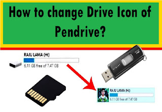
Pendrive is one of our must important storage device, where we store our documents or data. Normally, when we pluck our Pendrive to our PC, it displayed default icon every time. We can put our own photo or icon instead of default icon. To change the icon of removable disk / prndrive follow the following steps.  


Before following the steps we should have our own icon/photo and Pendrive.
Step 1: Right click on the picture or icon which you want to set as drive icon and click on Edit.
Step 2: Your picture will be open in Paint program. Crop the picture using select tool and crop tool. 


Step 3: Click on File > click on Save as > type the picture name (e.g myicon) > click on save as type > and choose 24-bit Bitmap (*.bmp; *.dlb) > finally choose your location and click on save.
Step 4: Now open Notepad program (press Win+R key >type :  notepad in press enter key) and type the following code, and save it with autorun.inf file name. 
            [autorun]
             icon = myicon.bmp

Step 5: Copy the picture file (myicon.bmp) and autorun.inf file. 
        

Step 6: Paste it in Removable Drive (Pendrive)


Step 7: Remove your Removable Drive (Pendrive) and insert again. Your drive icon will be changed.

It's look like unique then others, Isn't it? (You can hide myicon.bmp and autorun.inf file)

Video Tutorial 


It specifies a rule for interpreting or modifying the address field of the instruction before the operand is actually referenced. It helps for 
  • Providing programming flexibility to the uses.
  • Using the bits in the address field of instruction efficiently

Types of Addressing Modes

1) Implied Addressing Mode
  • Address of operands are specified implicit in the definition of instruction.
  • It does not need to specify address of instruction
  • Example : Add x; Add y; 
2) Immediate Addressing Mode: 
  • Instead of specifying the address of operand itself is specified in the instruction. 
  • No need to specify address in the instruction. 
  • However, operand itself need to be specified. 
  • Sometimes, require more bits to be address. 
  • Fast to acquire an operand
3) Register Addressing Mode
  • Address specified in the instruction is the address of register.
  • The instruction has the address of the Register where the operand is stored.
  • Shorter address then memory address.
  • Shorter instructions and faster instruction fetch
  • Saving address field to access to the operands 
  • It has very limited address space
4) Register Indicate Addressing Mode
  • In this mode, the instruction specifies the register whose contents give us the address of operand which is in memory. Thus the register contains the address of operand rather than the operand itself. 
  • Instruction specifies a register which contains the memory address of operand 
  • Saving instruction bits since register address is shorter than memory address
  • Slower then register and memory addressing 
  • Example:   EA = contend of R
5) Auto increment or Auto Decrement address mode
  • In this mode the register is increment or decremented after or before its value is used. 
  • Instruction specifies the memory address which can be used directly to access the memory. 
  • Faster then the memory addressing mode
  • Too many bits are needed to specify the address for a physical memory space.
  • Example:   EA = IR (Address)
6) Direct Addressing Mode
  • In this mode, effective address of operand is present in instruction itself. 
  • Single memory reference to access data
  • No additional calculation to find the effective address of the operand
  • For Example: Add R1, 4000, In this the 4000 is effective address of operand.  
        Note : Effective Address is the location where operand is present
7) Indirect Addressing Mode
  • The address field of an instruction specifies the address of a memory location that contains the address of the operand. 
  • When the abbreviated address is used large physical memory can be addressed with the relatively small number of bits.
  • Slow acquire operand because of an additional memory access. 
  • Example:    EA = M[IR )address)]
8)  Relative Addressing Mode
The address field of instruction specifies the part of the address which can be used along with a designed register to calculate the address of the operand. 
  • Address field of the instruction is short
  • Large physical memory can be accessed with a small number of address bits.
  • There are three addressing mode
There are three different other register addressing mode:
  1. PC Relative addressing Mode (EA = IX + IR(address))
  2. Indexed Addressing Mode (EA = IX + IR (address)) / [IX is indexed register]
  3. Base Register Addressing Mode (EA = A + (R) 


A number system is a system for expressing numbers that is mathematical notation used for manipulating other countable things. The numbers are represented in different based system in different situation. The decimal number system is used for human counting but not role in machines. Binary numbers are used in modern digital devices. Octal and Hexadecimal number system are just packages of 4 binary bits. In computer science we have to study four number systems. They are


  1. Binary Number System (0, 1) / Base or radix = 2
  2. Octal Number System (0 to 7) Base or radix = 8
  3. Decimal Number System (0 to 9) Base or radix = 10
  4. Hexadecimal Number System (0 to 9 and A to F) Base or radix = 16
The following table shows the number system equivalent to one another. 
Binary
Octal
Decimal
Hexadecimal
0000
0
0
0
0001
1
1
1
0010
2
2
2
0011
3
3
3
0100
4
4
4
0101
5
5
5
0110
6
6
6
0111
7
7
7
1000
10
8
8
1001
11
9
9
1010
12
10
A
1011
13
11
B
1100
14
12
C
1101
15
13
D
1110
16
14
E
1111
17
15
F


  1. Binary Number System : Any number having base or radix 2 and the number consists 0 and 1 only are called binary number system. E.g:  1110­2, 10012, 1110012
  2. Decimal Number System: Any number having base or radix 8 and the number consists 0, 1, 2, 3, 4, 5, 6 and 7 are called octal number system. E.g: 563­8, 12358, 57368
  3. Decimal Number System: Any number having base or radix 10 and the numbers consists 0, 1, 2, ........ 9 are called decimal number system. E.g : 196­10, 25810, 123610 
  4. Hexadecimal Number System : Any number having base or radix 16 and the number consists 0, 1, 2, 3, ...... 9 and character consist A, B, C, D, E and F are called hexadecimal number system. Where A=10, B=11, C=13, D=14, E=15 and F=15. E.g : 25A­16, 156B16, 9D16  

Binary Calculation

The modern digital computer system performs every calculations in the form of binary format. They present 0 or 1, on or off, presence and absent. It represents the status. 
Binary Addition: 
Binary addition is performed in a similar way to decimal addition.
Binary Addition
X
Y
X+Y
0
0
0
0
1
0
1
0
0
1
1
10 (with a carry of 1)
Example: a) Add 110102 1001­2    b) 1111011101­2
Binary Subtraction: 
Binary subtraction, similar method is adopted as in decimal system. 
Binary Subtraction
X
Y
X-Y
0
0
0
0
1
1 (with a borrow of 1)
1
0
1
1
1
0
Example : a) 10010 - 1011          b)    1101101 - 111101
Binary Multiplication 
Binary multiplication is easier since there is no number as "carry" value. The following rule is adopted in binary multiplication. The values are added column wise as in binary addition. 
Binary Multiplication
X
Y
X*Y
0
0
0
0
1
0
1
0
0
1
1
1

Example:  a)   11101 x 111          b)    100011 x 110  


Binary Division
Binary Division is similar to decimal division. If a number cannot be divided, put 0 to the quotient. If division is possible put 1 to the quotient. Multiplication and subtraction is as discussed in binary multiplication and binary subtraction.  
 Example: a) Divide 1011 by 11               b)  111 by 11
For Practice : 

  1. Binary Addition
    • 1011 + 11 
    • 11111 + 10101
    • 11100 + 10111
  2. Binary Subtraction
    • 1011 - 1000
    • 101010 - 11001
    • 11011 - 1010 
  3. Binary Multiplication
    • 1110 x 110
    • 1101 x 111
    • 11101 x 1011
  4. Binary Division 
    • 10011 by 110
    • 11100 by 1110
    • 1110 by 110

MKRdezign

Contact Form

Name

Email *

Message *

Powered by Blogger.
Javascript DisablePlease Enable Javascript To See All Widget